Pose Estimation Robot

Introduction

The purpose of this project is to create a robot that is capable of mimicking pose of people in real-time from video. This technology is a growing field of interest for machine learning and robotics engineering. Currently, the most difficult part of this problem is the computer vision task, where a robot must predict the exact position of a person's joints from a given camera frame or video. A potential application for this technology could be the ability to teach a robot complex tasks through example videos.

Below are some results from the project. The robot is capable of mimicking human poses in real time via a video stream from a webcam. The monitor to the left of the frame renders the human model that the robot perceives, which the robot then replicates. The later sections of the post go into the details of how the robot works and was built. Sections are ordered by the flow of the processing stream; first the visual system is described, then the process which links vision and motor control, and finally the electrical and mechanical design of the robot. Code that was developed to run the robot can be found here.

Video 1: Wave

Video 2: Run

Video 3: Arms Up

Video 4: Football Throw

3D Human Pose Estimation

Estimation of human joint coordinates from an image is a hard problem to solve with classic computational methods. As is typical with many problems in computer vision, the current best approach is to use deep neural networks to learn the correct representation. The robot uses the method developed in "3D Human Pose Estimation in Video with Temporal Convolutions and Semi-Supervised Training" [1] to generate the cordinates of each joint in 3D space. In this section the paper is briefly reviewed, along with the necessary modifications made to the original code that was released with this paper.

Paper Summary

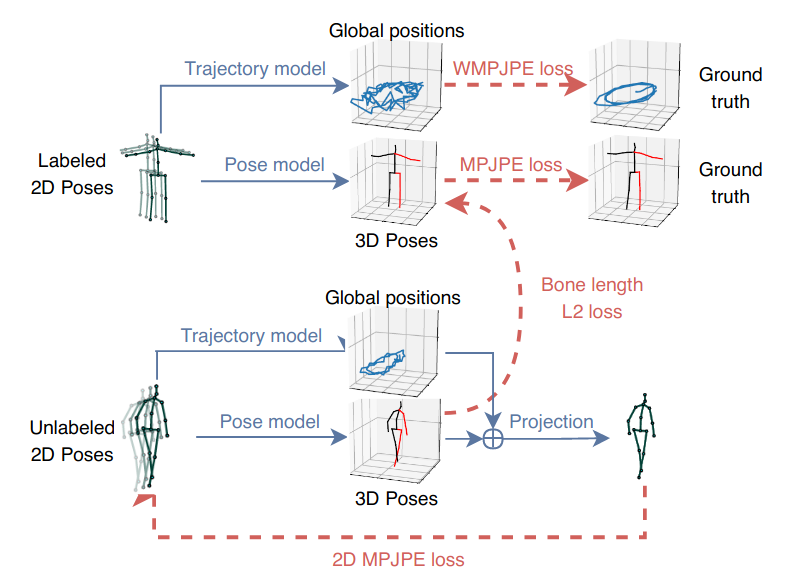
A common practice for 3D pose detection is to first estimate a 2D skeleton from an image, and then to use this representation to predict the final 3D coordinates. While this method has the issue that than mutiple 3D skeleton frames could be cast to the same 2D model, in practice it achieves state of the art performance. Given this, the paper uses the pre-trained Detectron2 [2] network developed by Facebook AI to perform the initial 2D skeleton frame detection from each image in a video stream.

Next, a neural network that can predict the 3D pose from the output of the Detectron2 model is required. The authors opt to use a fully convolutional method that performs temporal convolutions on a series of past predictions from the Detectron2 model. This is motivated by the assumption that past frames can give additional information about how to generate the 3D model. For a real time implimentation, it is important that causal convolutions are used, meaning that the network is trained and run by using only information in the past. The difference between the two types of convolutions can be seen in Figure 1 below. The benefit of using a fully convolutional method like this is that the computation is fast, and efficently scales to consider exponentially many frames in the past, with just a linear increase in network parameters.

Figure 1: Symmetric vs Causal Convolutions

For training, the authors use a combination of supervised and semi-supervised learning. For supervised learning the Human3.6M [3] dataset was used, which consists of actors performing a variety of sequences like giving someone directions, or walking a dog, which are annotated with the coordinate information of every joint. As for the semi-supervised learning, unlabelled video data is used. Frames are passed into Detectron2, and the 2D joint model is then passed through the neural network to generate a 3D skeleton. This is then projected back into the 2D camera view, where the network is trained to minimize the difference between the 2D representations. In order properly cast between 3D space and 2D camera space, a trajectory model is created to track the global position. Finally, an additional term is added to the loss function to encourage the network to predict joint coordinates with bone lengths that are consistent with the training data. Figure 2 shows a summary diagram of the training sequence.

Figure 2: Training Routine

Code Adaptation

A few changes and additions needed to be made to the code released by the authors in order to integrate the neural network models with the robot. First, the code was not set up to be run in real-time, and made use of three different programs that were not integrated. The scripts were cut down to reduce un-needed code, and were updated to allow for streaming input that could make use of the causal convolutions. A fast camera capture program was used to collect images from a webcam, where the frames were then passed through Detectron2 and the 3D pose network. Currently, the code is undergoing further update to include real-time batch processing and multi-camera support. Given that some poses are easier to detect at different camera angles, the use of multiple cameras will allow for a more accurate prediction system. Furthermore, this addition will not effect the runtime due to the parrallel nature of batch processing on GPU's.

In order to control the robot to mimick the 3D poses from the neural networks, it was required to create a method that converts the joint positions into motor angles. While typically, one might use inverse kinematics to control a robot to reach a desired position, it was decided that the relative joint angles would allow for a more visually pleasing imitation of the human pose for this application. A program was created that constructs the pose as a collection of vectors, and uses fast matrix operations to compute the motor angles required to mimic the pose. The output of this process can be see below in Video 5, where the pitch, roll and yaw signals correspond to the shoulder joint at Figure 3.

Video 5: Motor Angles

The final output of the main processing pipeline is simply a small array of target motor angles at each given frame. This full program is run of a powerful desktop computer that is networked to a raspberry pi which is used for the robot controller. The control law is implimented by a simple feedback loop, which was fined tuned for each motor type.

Robot

For the mechanical design, the primary component of the robot is the arm mechanismn. The design roughly follows the human anatomy, which has three degrees of freedom at the shoulder joint, and one at the elbow. Both servo and classic DC motors used, depending on the torque, range of motion, and required speed for the given degree of freedom. For example, the elbow joint has low torque, low range of motion, and high speed requirements. Thus, a high speed servo was chosen, with low weight in order to reduce torque on the shoulder motors. An additional heavy DC motor at the base of the robot to perform the waist rotations.

Fig 3: CAD Design of Arm

Fig 4: CAD Design of Torso

The electrical design has two sub-circuits, the first uses an external 120V AC to 12V DC for the DC motors, and the second uses another external 120 AV to 5V DC for the servo motors which is needed because the raspberry pi cannot supply enough current to the 5V line. An expansion board connects the servos to the raspberry pi, which allows for a simple control signal to be sent, as the control loop is done on chips inside the servos. To drive the motors, H-bridges are needed for both forward and reverse rotation, as well as lines for the positional encoders, which are used to inform the control program on the raspberry pi. For safety purposes, the external power supplies are connected to a switch which can be used to manually power off the robot.

Fig 5: Electrical Design

References

[1] 3D Pose Estimation Paper: https://arxiv.org/pdf/1811.11742.pdf
[2] Detectron2: https://github.com/facebookresearch/detectron2
[3] Human 3.6M Dataset: http://vision.imar.ro/human3.6m/description.php